ZX type variable microporous aeration hose
ZX type variable microporous aeration hose
ZX type variable microporous aeration hose
- Product Details
- Product parameters
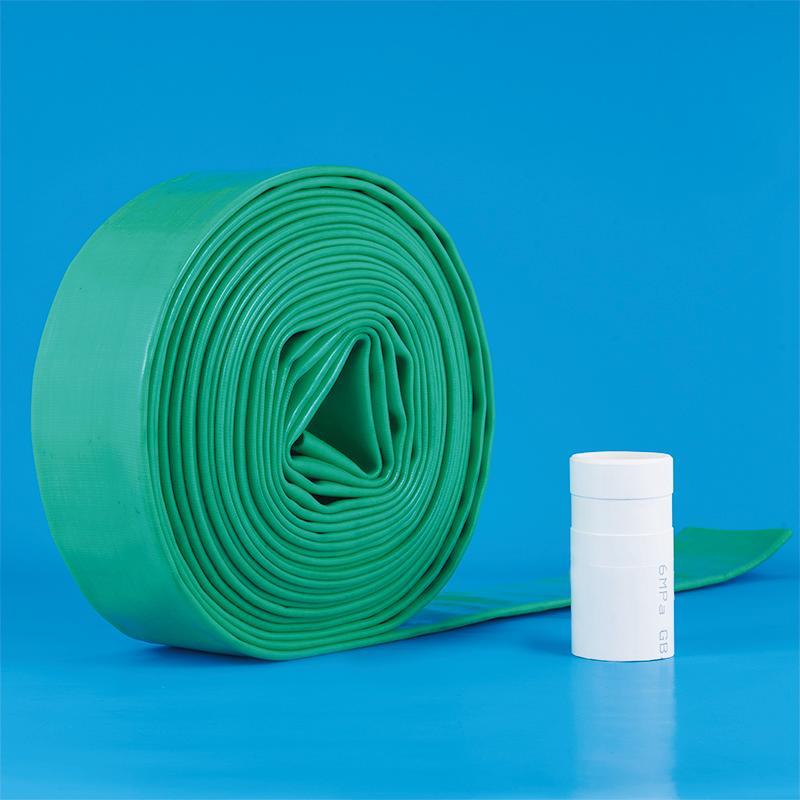
Product overview
At present, in the process of biochemical treatment of sewage, whether it can provide sufficient dissolved oxygen is the key to providing biochemical treatment effect and economic benefits. Since there are many types of aeration devices, the effect of oxygenation in water is also different. Exploration and research, successfully developed a kind of uniform air distribution, air in the process of rising at the bottom of the pool through the aerator to produce swirl, diversion, collision, cutting and other physical effects, so that the bubbles are fully broken and thin, so as to achieve good performance. A new type of aerator with high oxygen transfer efficiency, low resistance and no clogging - rotary mixing aerator.
Aeration hose design requirements
1. Activated sludge method and SBR method
①The first method: The hose is fixed with a special bracket, and the bracket is fixed with the bottom of the pool with expansion bolts. The bracket is made of Φ10 round steel, with a height of 40mm, a spacing of 500mm, and a hose spacing of 500mm.
②The second method: G1/2" galvanized pipes are installed at the bottom of the pool (equivalent to the lower frame of the filler), the distance between the galvanized pipes is 500mm, the direction of the hose and the frame must be perpendicular, and the hose is installed on the frame close to the frame. The central axis of the tube is 500mm away from the bottom of the pool.
2. Biofilm aeration tank and membrane oxidation ditch
①The hose is under the packing frame and is perpendicular to the frame. The distance between the hose and the outer frame is 10mm, and the distance between the hoses is 500mm.
②The central axis of the air distribution pipe (horizontal pipe) is on the same horizontal plane as the central axis of the hose, and the hose is 500mm away from the bottom of the pool.
③The diameter of the air distribution pipe (horizontal pipe) is DN120~200mm, the diameter of the intake pipe (vertical pipe) is DN100~150mm, and the flow rate of the intake pipe is ≤8m/s.
3. Three design methods for the tail of the hose (take ZX-65 as an example)
①Single head air intake, the other end (tail) is sealed with stainless steel, and fixed with the reserved rope at the tail of the hose and the embedded parts on the pool wall.
② One end is inhaled, and the other end is connected to the tail of the hose with a DN80 connecting pipe.
③Intake air at both ends at the same time.
④The DN25 sewage pipe can be set on the tail connecting pipe to lead out the water surface, and the valve can be opened to discharge the sewage if necessary.
4. Reference values of actual engineering design parameters
①The actual project usually chooses ZX-65 type. The length of the hose is generally 5 to 40m.
②When the effective water depth (the distance from the center of the hose to the water surface) is 4 meters and the aeration rate is 3m3/h:
The oxygen utilization rate of the first generation variable hole aeration hose (ZX-65 type) is 10-12%;
The oxygen utilization rate of the second generation spiral hole aeration hose (ZX-65 type) is 14-18%.
Aeration hose installation drawing

Specification for installation of aeration hoses
1. Installation precautions
①The hose must not be dragged or thrown, and the air line must be blown clean.
②The error of the central axis of the special fixed bracket in the activated sludge method is less than 10mm, and the horizontal error of the middle and lower frames of the membrane aeration tank is less than 105mm.
③Single-head air intake first fix the tail, and then cut off the middle super-long part from the head.
④ If a sewage pipe is used at the tail, the sewage pipe must be extended into 2/3 of the tail ventilation pipe.
⑤ After installation, it is strictly forbidden to weld around it.
2. Installation method
①Head installation: the front of the hose is facing up, the hose is put on the steel joint, the throat hoop is then clamped into the threaded groove of the steel joint, and the nuts at both ends are evenly tightened.
②Middle installation: without packing frame, the hose passes through the special fixing bracket; with packing frame, use special fixing ropes (provided by the manufacturer) every 500mm to bind and fix the hose under the packing frame.
③ Tail installation: The reserved rope at the tail of the hose is connected and fastened with the embedded parts on the pool wall. The hose must be straightened without twisting, swinging or arching in the middle.
Regardless of the intake method, the excess hose in the middle must be cut off.